The master thesis covers a task of Ambient Assisted Living (AAL) and is conducted in the Laboratory for Autonomous Systems at the Munich University of Applied Sciences (MUAS).
Work Objective:
The master’s thesis deals with the grasping and relocation of objects by a domestic assistive robot of the Laboratory for Autonomous Systems at the Munich University of Applied Sciences. The goal is to autonomously navigate the robot to a table and then pick up an object on this table and place it at a different position.
For this task, the robot relies on data of the environment which it picks up using a variety of sensors.
Master thesis result
Roboter
The internal nickname of the robot used throughout this master thesis is called Robert.
Drive
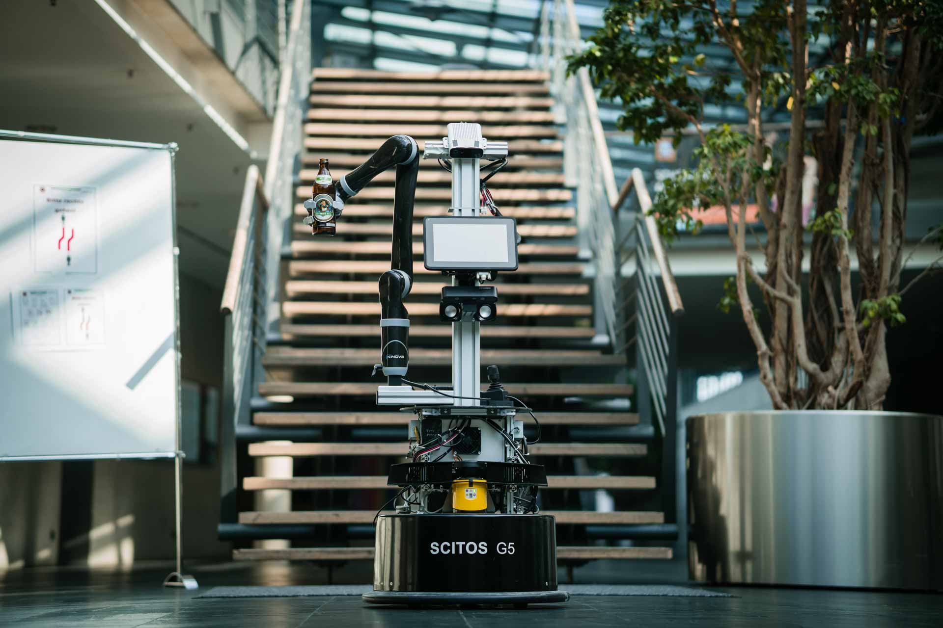
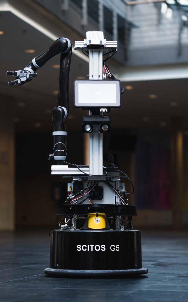
The robot is based on the Scitos G5 mobile platform from MetraLabs. This represents the lower part of the robot and enables its movements. Due to the differential drive, the robot can turn on the spot and move in all directions. This type of drive is widely used, for example in vacuum robots.
The platform also contains the batteries that supply the entire robot with power during autonomous operation.
Arm
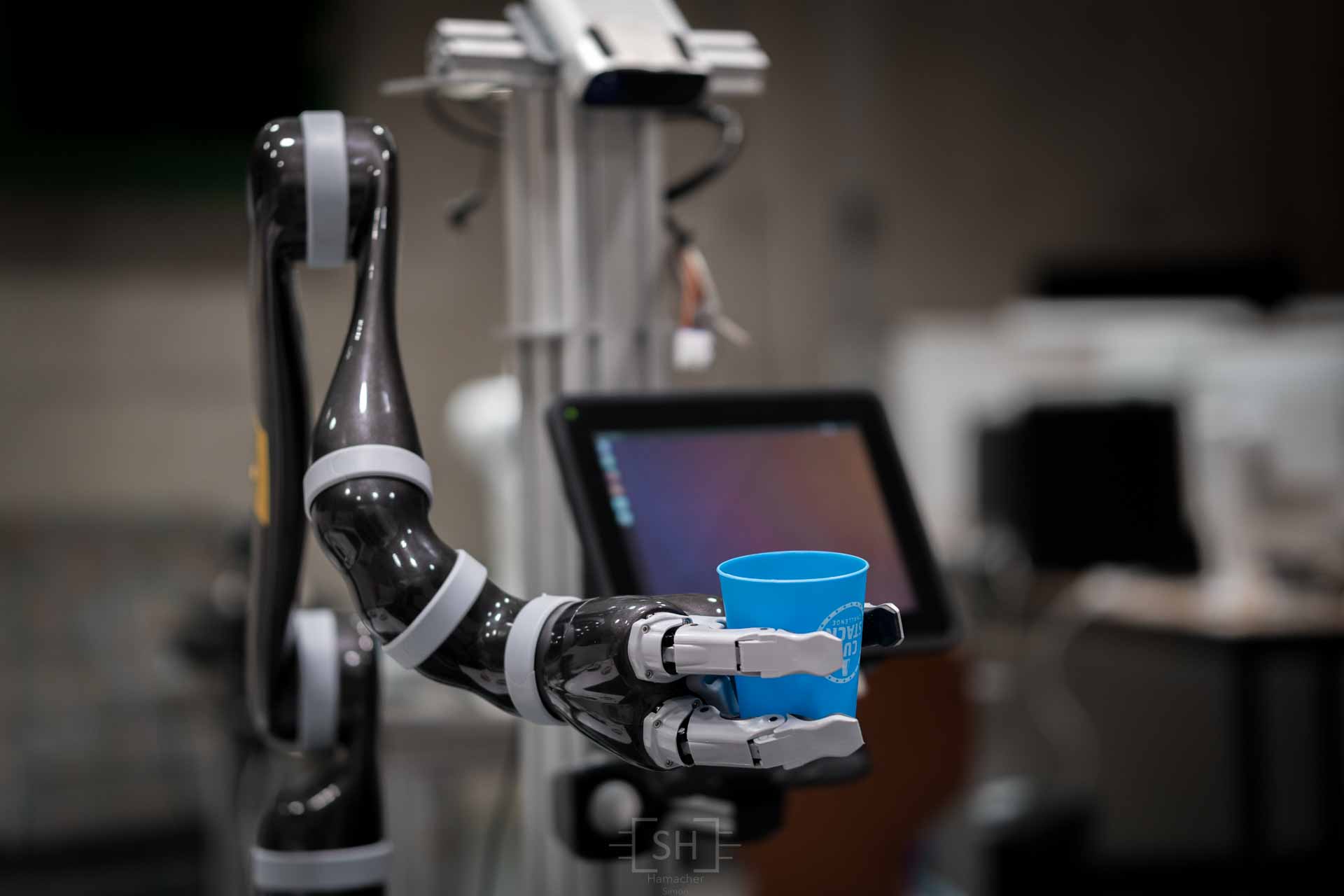
The j2ns300 gripper arm from Kinova enables the robot to grasp objects. This arm has 6 degrees of freedom (DOF). The gripper has three fingers which can be controlled individually to hold objects securely.
Measurement technology
To enable the robot to collect data about its environment, it is equipped with a variety of measurement technology. If only to avoid a possible collision of the moving robot with objects standing around, it is essential that the robot knows its surrounding.
-
Bumper: The Scitos G5 mobile platform has a rubber bumper all around that detects collisions and stops the drive in the event of a collision.
-
Scanner: They also serve to prevent collisions of the robot while driving. Scanners are installed in the front as well as in the back of the robot to provide a full 360° coverage of the driving area. An overview of the technical data of the scanners is listed in the table below:
Type Range Scan angle Mounting position Laser range finder SICK S300 30m 270° front 2D LiDAR sensor TIM551 10m 270° back -
Depth imaging camera: The robot obtains its 3D impression of its environment using one Microsoft Azure depth camera. Using the time of flight (TOF) method, the camera can measure the distance of points to the camera. Thus, the camera not only captures the color images (RGB) but additionally the depth information of the pixels as a point cloud. This data (color image and depth information) can be used e.g. to detect objects in space.
Hardware and Software of the Robot
The heart of the robot are two Linux PCs running Ubuntu. These PCs are connected to each other via an Ethernet cable.
All components that are directly installed on the Scitos G5 Base are controlled via the C++ cross-platform framework MIRA. This includes the drive, the power management of the batteries and the scanners.
All other tasks of the robot are performed by the open source Robotic Operating System ROS. Tasks are e.g. the control and path planning of the arm, evaluation of the depth imaging camera, localization of the robot and creation of a map from the measurement data of the robot together with the odometry data of the chassis.
ROS and MIRA are connected through a node acting as interface between these two worlds.
Platform simulation
It is useful to allow the simulation of the complete robot. For this purpose a robot simulation program Gazebo is used. Gazebo has the great advantage that the virtual robot is very similar to the real robot allowing easy switching between the simulated robot and the real robot.
The simulation has the possibility to move the robot in space and to move the arm. Through suitable plugins all sensor data can be simulated so that the robot can be completely recreated.
Since the robot should not start in a completely empty room, the simulation offers to load a virtual world at simulation startup, which then represents the new environment of the robot.
In the following table the simulation of the robot is shown on the left. The robot is located in a world consisting of a table on which two cans are placed. All data about the robot is provided by Gazebo and managed via ROS.
The program RViz shown in the table on the right is a 3D visualisation program which can display all data of the robot. Here the robot is displayed in its current position, and the camera information is visualized and the depth information is illustrated by small cuboids.
| Gazebo – Simulation | RViz - Visualisation |
|---|---|

|

|
Reality
In reality, the simulation of the robot, representing the left part in the previous section, is omitted. It is now replaced by the real robot with its sensor data of the real environment. The right part (RViz), on the other hand, remains, only now the real data of the robot is represented.
| Robot | RViz - Visualisation |
|---|---|

|

|
Now it becomes clear whether the algorithms designed in the simulation can also prove themselves in practice.
In contrast to the simulation, real-time data from real sensors are now evaluated. This means that effects such as noise or other undesired artifacts not modeled by the simulation have an impact on the data.
Tasks performed as part of the master thesis
Simulation documentation.
- Creation of a Git repository
- Integration of the different simulations to one simulation with a large range of functions.
- Documentation of the already working functions and the outstanding functions as readme of the GIT Repository.
Commissioning of the drive and the laser scanner
- Understanding the connection of the Scitos-G5 Base via the MIRA framework to the ROS operating system of the rest of the robot.
- Configuration of the hardware of the drive and the laser scanner drivers.
Cartography
| Start of map recording | End of map recording |
|---|---|

|

|
- Use of the odometry and laser scanners of the robot.
- By driving the robot in space, the laser information of each position can be entered in a map. The algorithm that performs this task of mapping is called Gmapping.
- Colors of the maps are Gray for obstacle free, Black for obstacle (e.g. walls) and Dark green for areas not reached by the laser beams.
Localization
- This map is used for locating the robot and then for path planning.
- The generated map is loaded and the current position of the robot is used by the current laser scans (colored pixels). The algorithm used for this is AMCL.
- Below are two images. In the left image the position of the robot is very inaccurately determined, whereas in the right image the information from the laser scan coincides better with the obstacles from the map, which leads to a better localization.
| Robots with poor localization | Robots with good localization |
|---|---|

|

|
- Path planning: Based on the information from the map, the position of the robot in the map and the current obstacles detected by the laser scans, the robot can autonomously drive to targets on the map.
State machines to control the stunt

- The concept of ROS is based on different nodes that provide all the functionality of the robot in a network. For this it is important to use a sequence control, which takes over the timing and the chronological sequence of the activities.
- A state machine is used for precise coordination of the robot’s individual tasks.
- The ROS SMASH architecture represents a powerful state machine, which can be adapted depending on the application. Another advantage is the graphical representation of the state sequence. (see right)
- The state machine always has an active state, shown in green. Depending on the result of the active state, the subsequent state is then selected.
- The task of a node can be the initialization or the execution of a function, depending on what is useful for the program flow.
- The nodes shown in red are the end of the state graph
Existing functions:
Grasping objects
- If the robot is within range of an object, it uses the depth imaging camera to detect the object and determine its position.
- If the position of the object is known, the depth information is removed in the area of the object and a green cylinder is displayed instead of the object (as can be seen below).
- The computer tries to calculate a sensible path (trajectory) for the gripper arm to be able to grasp the object safely.
| RGB camera image of table and object | Depth image with detected object (green cylinder) |
|---|---|

|

|
If you want further information don’t hesitate to contact me!