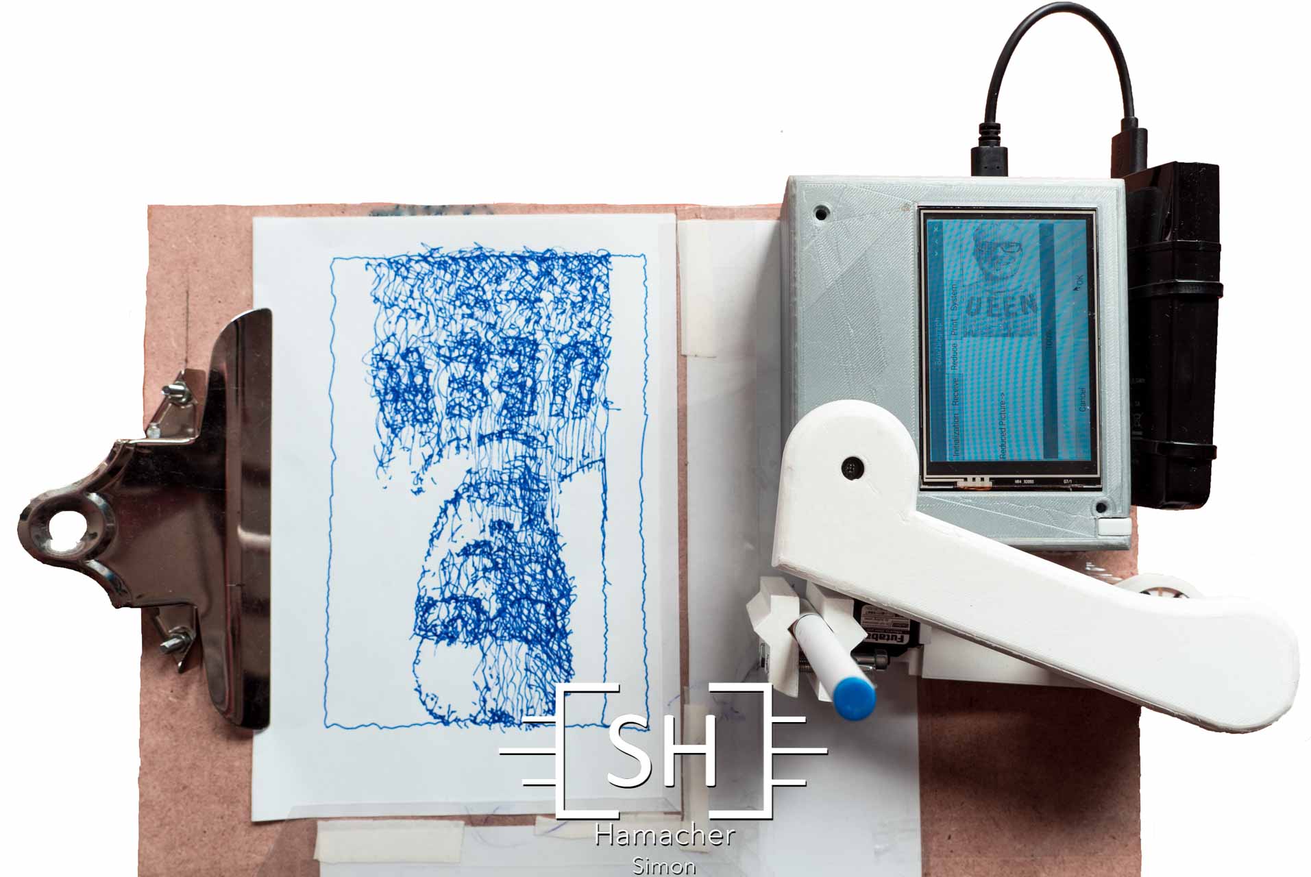
The Brachiograph can print any picture on a DIN A5 paper or, as a party gag, on a beer coaster.
Want to see the plotter in action?
The Brachiograph has a 3D printed body and a custom made Raspberry PI shield PCB, which controls three servos (engines), one each for the two joints maneuvering the arm in the X,Y plane and the third one to control the pen up resp. pen down movement.
The software consists of a user friendly Android app, a touchscreen GUI controlling the Raspberry PI, plus an improved calibration routine leading to pictures of decent quality.
My contributions to this successful project:
1. Android App:


This Android App has been developed using the official Android integrated development environment (IDE) Android Studio.
Features:
- WiFi connection from ordinary mobile phone (Android OS) to the Raspberry PI
- Collection of all needed permissions (Android OS)
- Picture taking using the default Android camera app and saving it to the internal device storage.
- Visualization, compression and base64-decoding as preparation for the submission to the Brachiograph.
- Submission to Brachiograph (thread-based architecture).
2. Intuitive GUI (PyQt5):

It handles the following tasks on the Raspberry Pi:
- The application initializes the Brachiograph Back-End to the users liking.
- It handles the reception of the picture using a WiFi thread.
- It converts the picture to a sequence of lines using edge detection algorythms.
- It translates these lines PWM signals.
- It outputs those PWM signals to the servos yielding the printed picture.
3. Higher precision of the servo signals through a dedicated PWM chip (over PWM signal generation by the Raspberry PI itself):
In order to achieve a nicely printed picture the plotter arms needs to be accurately positioned at each coordinate and the respective vertices. The pulse lengths of the PWM signals represents the target angle of the joints.

Highly accurate PWM-signal are generated using a 16-Channel 12-bit PWM/Servo Driver (PCA9685). This chip is part of the PCB-Shield for the Raspberry, with I2C as the communication protocol.
4. System Integration ➔ bring the pieces together and finetune for optimal results:
The project consisted of the following four tasks. My responsibilities were tasks 3 and 4.

- CAD — 3D-modeling and -printing.
- Shield development — Design and layout of the PCB mounted on the Raspberry PI.
- Software — Creation of both the Android app as well as the app for the Raspberry PI, including significant improvements to the available Brachiograph Back-End libraries.
- System integration — One can imagine that the integration of the above tasks is everything else than trivial. Once the product worked I optimized the quality of the plot through advanced calibration and tuning routines.

If you want further information don’t hesitate to contact me!
Our project uses components from the Brachiograph Github project. I uploaded my findings and improvements to this repostory and they are availble under the following Git pull request.

